PinOne Mini Board
Introduction
The PinOne Mini board is a board that attaches to the PinOne and exposes many of the inputs/outputs in a way so that you can easily connect perephrials and other devices to your board. The board by itself supports the following options:
- 9 button inputs through JST-XH 2 pin plugs
- Plunger input through pluggable screw terminals
- 2 high power outputs with solenoid life extenders to connect solenoids
- JST-XH pins for lighted button outputs (5 RGB and 4 single LED buttons) -- all powered from the USB port, so no external power supply needed to operate
- Header pins for connecting the PinOne Mini expansion boards to add an additional 10 high power outputs so you can connect more toys and a shaker motor as well as an additional 4 button inputs.
- Header pins for connecting the expansion boards to power the light bar or add another bank of 16 high power outputs to your cabinet
- Header pins to easily connect the service board or add additional buttons to the PinOne
- All the normal PinOne features like nudge/tilt, and many software enabled features
Difference from PinOne Main board
A question I get a lot is how can I tell if I should get the PinOne Main board or the PinOne Mini board? They both use the same PinOne control board, so the software is the same, but there are some hardware differences to be aware of. Here are the differences of both of them
| Feature | PinOne Main | PinOne Mini |
|---|---|---|
| Number of High Power Outputs | 12 - 11 mosfet, 1 motor controller | 2 - With Life extenders |
| Number of Life Extenders | 0 - designed to be used with life extenders if adding solenoids | 2 - designed to have 2 solenoids plugged directly into board |
| Number of Button Inputs | 14 - screw terminal type | 9 - JST-XH connectors |
| Number of Low Power Outputs | 3 - Normally for knocker and 2 others | 16 - enough for 5 RGB buttons and 4 single color buttons |
| Input Voltage | 5V-36V | 5V-24V |
| Plunger input | Yes - dedicated 3 wire input | Yes - dedicated 3 wire input |
| Supports Button Board | Yes - Required for lighted button outputs | No - Buttons connect directly to board |
| Supports PinOne Mini Expansion Board | No - All high power outputs are on the PinOne Main Board | Yes - Used to upgrade the Mini to a PinOne Main like board |
| Supports Service Board | Yes | Yes |
| Maximum Supported Outputs | 63 | 63 |
| Maximum Supported Inputs | 24 | 24 |
Hooking it all up
Connecting to the PC
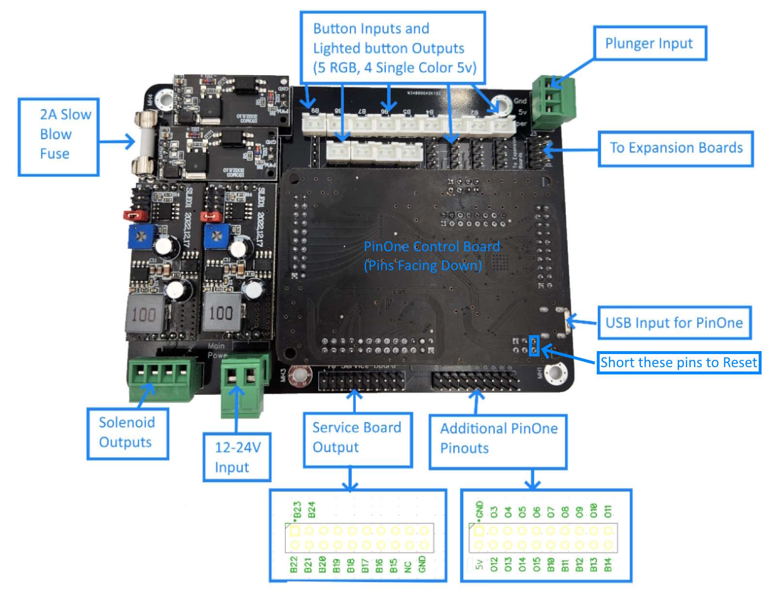
Connecting to your PC is simple through a USB cable. Once you plug it into the PC, you can use the configuration tool to activate all the outputs and configure the board. Unless you want to use the high power outputs, there is no need to connect a power supply
Connecting the buttons
For the buttons, the are labeled B1 through B9. B1-4 are RGB button inputs, B5-8 are single color LED button inputs and B9 is also an RGB button input.
VPX standard inputs:
- B1 = RGB Right Flipper
- B2 = RGB Right Magna
- B3 = RGB Left Flipper
- B4 = RGB Left Magna
- B5 = Extra Ball
- B6 = Coin
- B7 = Launch Ball
- B8 = Start
- B9 = RGB Fire
Expansion Board
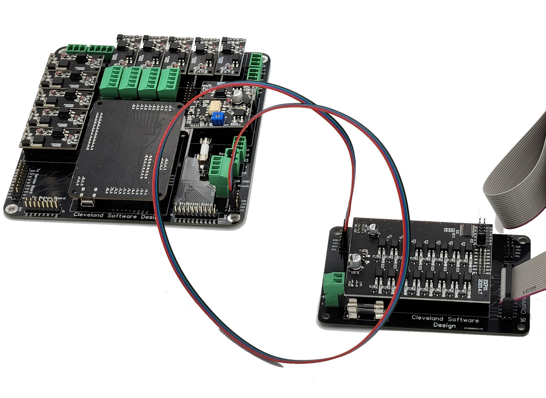
The Expansion Boards are connected to the 4 pin headers labeled "to expansion board" available on the main board. There are two rows of 4 pins, but only one of them needs to be used. You can connect up to two expansion boards to a PinOne board to add an additional 32 PWM outputs. (63 outputs total)
Be sure when connecting the 4 pin wires to the expansion board that the wires are connected the right way, as you can reverse the polarity when connecting. Ensure the black wire is going to the pin labeled "GND" on both boards
The low power expansion board is required to run the Light Bar
Mini Expansion board
The PinOne Mini expansion board allows you to connect additional outputs to the PinOne Mini so it has all the features of the PinOne Main (except still no button board support) It adds an additional 10 high power outputs (one is reserved for the shaker motor) and 4 additional button inputs.
Plunger
A Plunger can be connected directly to the mini board via the 3 pin connector where it is labeled "GND", "5V" and "WIPER" by connecting those inputs to the corrisponding inputs on the plunger board.
Service Board
This is as simple as just connecting the 20 pin ribbon cable from the PinOne main board to the Service Board.
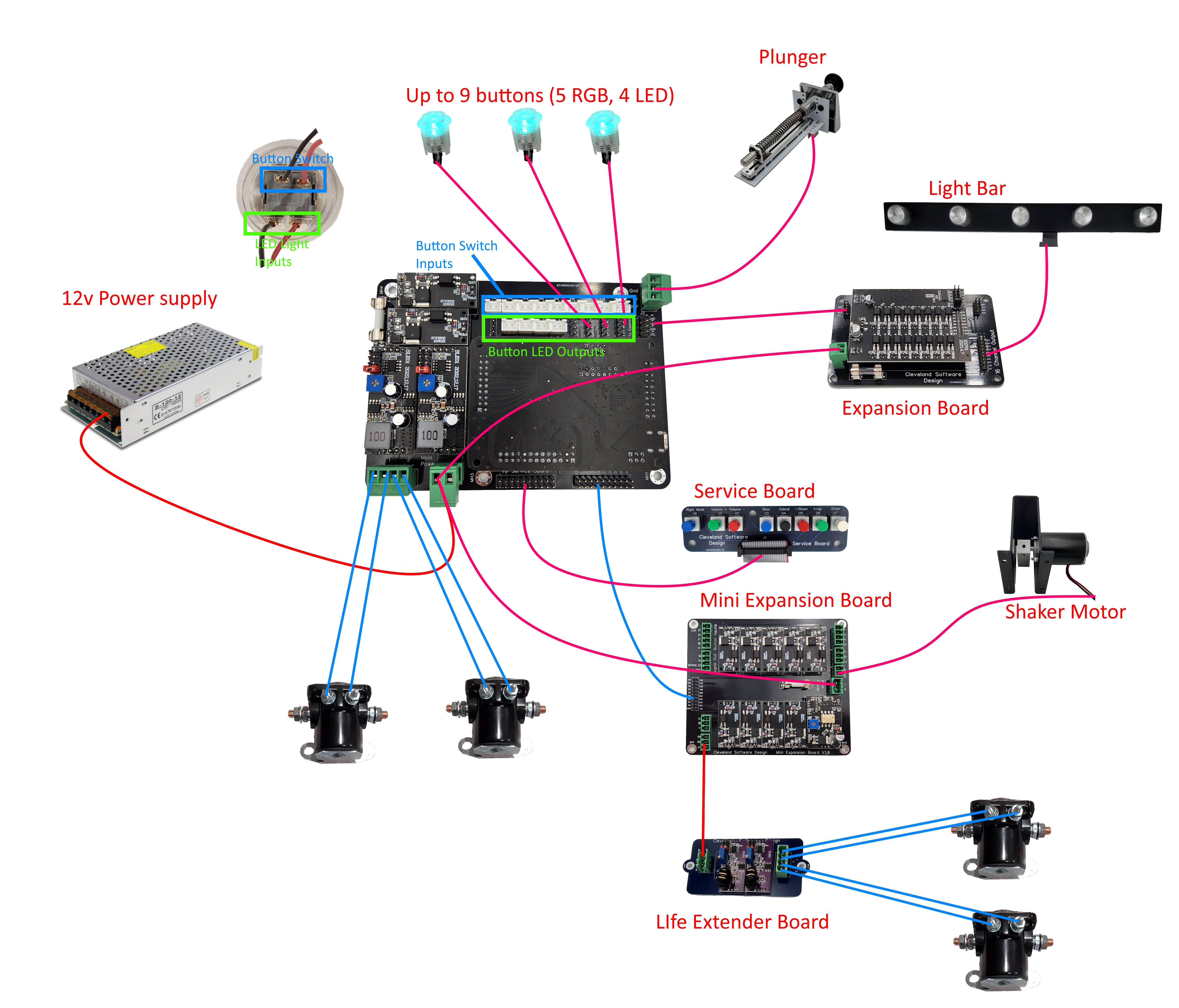
Connecting other devices
Below is a picture showing how to connect most devices to the PinOne Main board